
Electromagnetic Brake System

INTRODUCTION 

          With the technological enhancement a lot of new technologies are arriving in the world. Many industries got their faces due to the arrival of these technologies. An automobile technology is one of them. As a part of automobile, there are also innovations in brake. The commonly used types of brakes used in automobiles are drum and disc brakes. Various types of braking system used are hydraulic,pneumatic etc.
Magnetic braking forms the basis of growing technology. Braking system is generally classified based upon the principle of operation. The two major type of brake are frictional and electromagnetic retarder. The principle of braking in road vehicles involves the conversion of kinetic energy into thermal energy (heat).When stepping on the brakes, the driver commands a stopping force several times as powerful as the force that puts the car in motion and dissipates the associated kinetic energy as heat. Ineffective braking results in a lot of accidents. Brakes must be able to arrest the speed of a vehicle in a short period of time regardless how fast the speed is. As a result, the brakes are required to have the ability to generating high torque and absorbing energy at extremely high rates for short periods of time. Brakes may be applied for a prolonged periods of time in some applications such as a heavy vehicle descending a long gradient at high speed. Brakes must have the mechanism to keep the heat absorption capability for prolonged periods of time. The frequency of accidents is now-a-days increasing due to inefficient braking system. Hence braking system needs to be enhanced for effective and efficient braking. Electromagnetic brake is as new revolutionary concept . It is found that electromagnetic brakes can develop a negative power which represents nearly twice the maximum power output of a typical engine, and at least three times the braking power of an exhaust brake. These performance of electromagnetic brakes make them much more competitive candidate for alternative retardation equipments compared with other retarders. In this research work, with a view to enhance to the braking system in automobile, a prototype model is created and analyzed. It aims to minimize the brake failure to avoid the road accidents. It also reduces the maintenance of braking system. An advantage of this system is that it can be used on any vehicle with minor modifications to the transmission and electrical systems.

ELECTROMAGNETIC BRAKING 

Introduction 

     Electromagnetic brakes operate electrically, but transmit torque mechanically. This is why they used to be referred to as electro-mechanical brakes. Over the years, EM brakes became known as electromagnetic, referring to their actuation method. Since the brakes started becoming popular over sixty years ago, the variety of applications and brake designs has increased dramatically, but the basic operation remains the same. Single face electromagnetic brakes make up approximately 80% of all of the power applied brake applications. Electromagnetic brakes have been used as supplementary retardation equipment in addition to the regular friction brakes on heavy vehicles. Various Other types of Electromagnetic Braking System are: Electromagnetic Braking System With Brake Pads, Eddy-Current Braking System

Construction 

      There are three parts to an electromagnetic brake: field, armature, and hub (which is the input on a brake). Usually the magnetic field is bolted to the machine frame (or uses a torque arm that can handle the torque of the brake). So when the armature is attracted to the field the stopping torque is transferred into the field housing and into the machine frame decelerating the load. This can happen very fast (1-3sec).Disengagement is very simple. Once the field starts to degrade flux falls rapidly and the armature separates. A spring(s) hold the armature away from its corresponding contact surface at a predetermined air gap.The working principle of the electromagnetic brake is based on Right hand thumb rule


Working Principle 

       If a piece of copper wire was wound, around the nail and then connected to a battery, it would create an electro magnet. The magnetic field that is generated in the wire, from the current, is known as the “right hand thumb rule”. The strength of the magnetic field can be changed by changing both wire size and the amount of wire (turns). The fields of EM brakes can be made to operate at almost any DC voltage and the torque produced by the brake will be the same as long as the correct operating voltage and current is used with the correct brake. A constant current power supply is ideal for accurate and maximum torque from a brake. If a non regulated power supply is used the magnetic flux will degrade as the resistance of the coil goes up. Basically, the hotter the coil gets the lower the torque will be produced by about an average of 8% for every 20°C. If the temperature is fairly constant, and there is a question of enough service factor in the design for minor temperature fluctuation, by slightly over sizing the brake can compensate for degradation. This will allow the use of a rectified power supply, which is far less expensive than a constant current supply. Based on V = I × R, as resistance increases available current falls. An increase in resistance, often results from rising temperature as the coil heats up, according to: Rf = Ri × [1 + αCu × (Tf - Ti)] Where Rf = final resistance, Ri = initial resistance, αCu = copper wire’s temperature coefficient of resistance, 0.0039 °C-1, Tf = final temperature, and Ti = initial temperature.

Installation Location 

      Electromagnetic brakes work in a relatively cool condition and satisfy all the energy requirements of braking at high speeds, completely without the use of friction. Due to its specific installation location (transmission line of rigid vehicles), electromagnetic brakes have better heat dissipation capability to avoid problems that friction brakes face as mentioned before. Typically, electromagnetic brakes have been mounted in the transmission line of vehicles. The propeller shaft is divided and fitted with a sliding universal joint and is connected to the coupling flange on the brake. The brake is fitted into the chassis of the vehicle by means of anti-vibration mounting
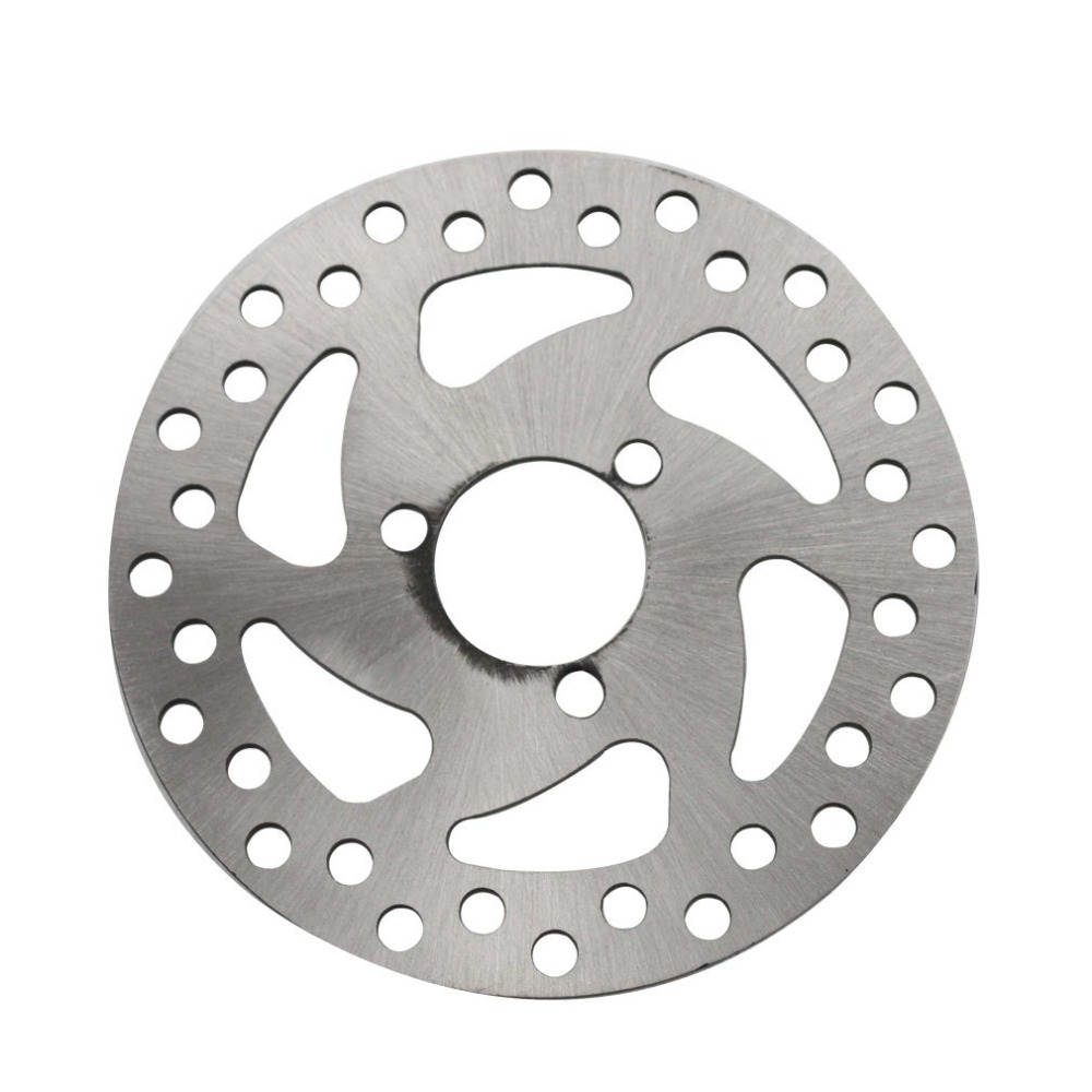
Disc brake plate


Disc liner 

      The lining is the portion of the braking system which converts the vehicle's kinetic energy into heat. The lining must be capable of surviving high temperatures without excessive wear (leading to frequent replacement) or out gassing (which causes brake fade, a decrease in the stopping power of the brake). Brake linings are composed of a relatively soft but tough and heat-resistant material with a high coefficient of dynamic friction (and ideally an identical coefficient of static friction) typically mounted to a solid metal backing using high-temperature adhesives or rivets.

Braking coil 

      An electromagnetic coil (or simply a "coil") is formed when a conductor (usually an insulated solid copper wire) is wound around a core or form to create an inductor or electromagnet. When electricity is passed through a coil, it generates a magnetic field. One loop of wire is usually referred to as a turn or a winding, and a coil consists of one or more turns. For use in an electronic circuit, electrical connection terminals called taps are often connected to a coil. Coils are often coated with varnish or wrapped with insulating tape to provide additional insulation and secure them in place. A completed coil assembly with one or more set of coils and taps is often called windings.

Tension Spring 

       A spring is an elastic object used to store mechanical energy. Depending on the design and required operating environment, any material can be used to construct a spring .When a spring is compressed or stretched, the force it exerts is proportional to its change in length. The rate or spring constant of a spring is the change in the force it exerts, divided by the change in deflection of the spring. That is, it is the gradient of the force versus deflection curve. An extension or compression spring has units of force divided by distance, for example lbf/in or N/m

Battery

        A battery is a device that converts chemical energy directly to electrical energy. It consists of a number of voltaic cells; each voltaic cell consists of two half cells connected in series by a conductive electrolyte containing anions and cations. One half-cell includes electrolyte and the electrode to which anions (negatively charged ions) migrate, i.e., the anode or negative electrode; the other half-cell includes electrolyte and the electrode to which cations (positively charged ions) migrate, i.e., the cathode or positive electrode. In the redox reaction that powers the battery, reduction (addition of electrons) occurs to cations at the cathode, while oxidation (removal of electrons) occurs to anions at the anode. The electrodes do not touch each other but are electrically connected by the electrolyte. Some cells use two half-cells with different electrolytes. A separator between half cells allows ions to flow, but prevents mixing of the electrolytes. Each half cell has an electromotive force (or emf), determined by its ability to drive electric current from the interior to the exterior of the cell. The net emf of the cell is the difference between the emf of its half-cells, as first recognized by Volta. Therefore, if the electrodes have emf and, then the net emf is in other words, the net emf is the difference between the reduction potentials of the half-reactions.

Alloy wheel  

     Alloy wheels have become considerably more common since 2000. Alloy wheels are automobile (car, motorcycle and truck) wheels which are made from an alloy of aluminum or magnesium. They are typically lighter for the same strength and provide better heat conduction and improved cosmetic appearance over steel wheels. The earliest light alloy wheels were made of magnesium alloys. Alloy wheels have long been included as standard equipment on higher-priced luxury or sports cars, with larger-sized or "exclusive" alloy wheels being options. The high cost of alloy wheels makes them attractive to thieves; to counter this, automakers and dealers often use locking wheel nuts which require a special key to remove. Most alloy wheels are manufactured using casting, but some are forged.

Electro-magnet 

        An electromagnet is a type of magnet in which the magnetic field is produced by the flow of electric current. An electric current flowing in a wire creates a magnetic field around the wire. To concentrate the magnetic field, in an electromagnet the wire is wound into a coil with many turns of wire lying side by side. The magnetic field of all the turns of wire passes through the center of the coil, creating a strong magnetic field there. The direction of the magnetic field through a coil of wire can be found from a form of the right-hand rule. The main advantage of an electromagnet over a permanent magnet is that the magnetic field can be rapidly manipulated over a wide range by controlling the amount of electric current.

Comments

Popular posts from this blog

GD&T basics

GD&T Symbols List Flatness Flatness GD&T Flatness is a common symbol that references how flat a surface is regardless of any other datum’s or features. It comes in useful if a feature is to be defined on a drawing that needs to be uniformly flat without tightening any other dimensions on the drawing. The flatness tolerance references two parallel planes (parallel to the surface that it is called out on) that define a zone where the entire reference surface must lie. Straightness Straightness actually has two very different functions in GD&T depending how it is called out. In its normal form or Surface Straightness, is a tolerance that controls the form of a line somewhere on the surface or the feature. Axis Straightness is a tolerance that controls how much curve is allowed in the part’s axis. This is usually called out with an included call to maximum material condition. Both callouts are very different from ea

ENGINE & WORKING PRINCIPLES

ENGINE & WORKING PRINCIPLES           A heat engine is a machine, which converts heat energy into mechanical energy. The combustion of fuel such as coal, petrol, diesel generates heat. This heat is supplied to a working substance at high temperature. By the expansion of this substance in suitable machines, heat energy is converted into useful work. Heat engines can be further divided into two types:

Applications and Processing of Metals and Alloys

Applications and Processing of Metals and Alloys       In the materials world we are living in, when making a new device/component, most often we come across a very familiar problem. This is nothing but select the right material. As learnt in earlier chapter, selection of material can play very important role preventing failures. Selection of material for a specific purpose depends on many factors. Some of the important ones are: strength, ease of forming, resistance to environmental degradation, etc. Another dimension an engineer should be aware of it is how to tailor the required properties of materials.