Definition of automobile

brake system
Actually, vehicle can be regard as energy conversion device, which
transfers the momentum into heat, in other words, which transfers the
kinetic energy into thermal energy. The brakes are used to reduce the
speed of the vehicle, and the speed of conversion determines the rate
of the vehicle slows down.
The basic physics principle used in brake system
As we know when we step the brake pedals or handbrakes, the cars transmit the force from our feet or hands to the brakes. Actually the car commands a stopping force ten times as powerful the force that puts the cat in motion. Because the brakes need a much greater force than drivers could apply with legs, the car must multiply the force of the foot. How could it be achieves? These two physics principles could be used: Leverage and Hydraulic system. And how do the brakes transmit the force to the tires? How do the tires transmit the force to the road? Both answers are using friction. Therefore, this part will introducce these three physics principle by first: Leverage, Hydraulics, Friction.Leverage
As the picture below shows, there is a force applied on the left end of the lever. The length of the left end is twice (2X) as long as the right end (X). Therefore, there is a force 2F on the right end. And it acts via the distance (Y), while the left end moves twice (2Y) as long as the 3 right end. Consequently, with the change of the relative lengths of the left and right ends of the lever, the multipliers are also changing.
Hydraulics system
In addition, a hydraulic system is applied the brakes. The hydraulic system connects the brake pedal to the brake parts at each wheel. The basic hydraulic system principle is simple. We can regard it as a process that force applied at one point is transmitted to another point by using an impressible fluid, which almost always is an oil of some sort.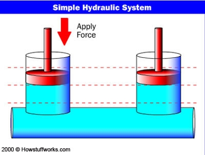


Friction
Friction is measured on how hard it is to slide one object over another. In the figure blow, both of the blocks are made from the same material, but one is heavier. Image which one will be harder for the bulldozer to push? The idea is the heavier one.
So the amount of force it takes to move the given block is proportional to that block's weight. The more weight, the more force is required. This concept applies for devices like brakes and clutches, where a pad is pressed against a spinning disc. The more force that presses on the pad, the greater the stopping force.
Basic components of the brake system
The brake system is composed of the following basic components: the energy-supplying device, the control device, the transmission device,the brake and additional retarder device, brake line (connecting different devices), and ABS (Anti-lock Braking System)
The energy-supplying device
The energy-supplying device means supplying and adjusting the necessary energy of braking. According to the types of energysupplying, there are three types used in automobile braking system: muscular energy braking system (non-power braking system) When we step the brake pedals or the handbrakes, the cars transmit the force from our feet or hands to the brakes. The force from driver supplies the basic energy to brakes. This is non-power braking; it just uses the force from human. For example, the bicycle is only using the no-power braking system to supply energy.energy assisted braking system (power assisted braking system)
The power assisted braking system use the force from drivers and the kinetic energy of engines together. The braking force of power assisted system increases through using the vacuum booster unit. Atmospheric pressure helps to push the brake pedal. Thus, less muscle effort is required. In spark-ignition engines, vacuum is generated through connecting intake manifold to the engine, while the diesel engines use the vacuum pump. non-muscular energy braking system (power braking system) The power braking system only uses the engines for transforming the kinetic energy into the potential energy of the atmospheric pressure or the hydraulic pressure.The control device
The main two control devices of braking systems are the service braking system and the parking braking system. They have separate control and transmission devices.The services braking system is footoperated, while the parking braking system is hand-operated. The service brake acts to slow, stop, or hold the vehicle during normal driving. They are foot-operated by the drivers pressing or releasing the brake pedal. The primary purpose of the brake is to hold the vehicle stationary while it is unattended. The parking brake is mechanically operated, when a separate parking brake foot pedal or hand lever is set.The transmission device
The transmission device is used to transmit the brake energy to brake actuator components. According to different transfer modes, the transmission device includes mechanical braking system, hydraulic braking system and pneumatic braking systemThe brake
According to the different functions of braking system, two types of brakes are used in modern cars: drum brakes and disc brakes. All cars used disc brakes on the front wheels, most cars use drum brakes on the rear wheels. In other words, the typical brake system consists of disc brakes in front and either disc or drum brakes in the rear connected by a system of tubes and hoses that link the brake at each wheel to the master cylinder. The basic components of drum brakes include: brake drum, an expander, pull back springs, a stationary back plate, two shoes with friction linings, and anchor pins.
Main types of drum brakes include: Simplex drum brake (Leading trailing shoe brake), Duo-trailing shoe brake (Two trailing shoe brake), Double leading shoe brake, Duo-duplex drum brake (Duo two leading shoe brake), Uni-servo drum brake, Duo-servo drum brake. Instead of a drum, the disc brake has a metal disc and a flat shoe or disc-brake pad, which is located on each side of the disc
Comments
Post a Comment